When it comes to air pollution, dust and smoke are just one of the numerous factors to consider.
Not only that, but wildfires have grown increasingly common in recent years as a result of climate change.
According to a recent study from the National Interagency Fire Center (NIFC), there were 58,733 wildfires in the United States in 2021, burning more than 7.13 million acres.
As a result, in this post, we’ll show you how to connect the GP2Y1014AU0F Dust Sensor to an Arduino to provide basic particle detection to your project.
Dust Sensor Pinout for the GP2Y1014AU0F
V-LED, LED-GND, LED, S-GND, VOUT, and VCC are the six pins on the GP2Y1014AU0F Dust Sensor module.
To measure the PM in the air, we must link the analogue output of this sensor to the ADC of a microcontroller.
The GP2Y1014AU0F Dust Sensor’s pinout is as follows:
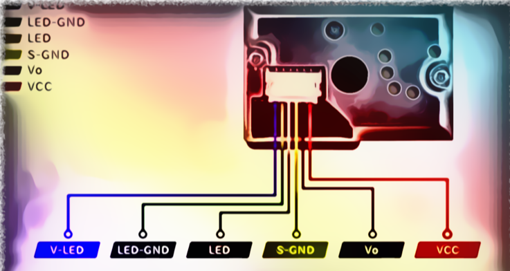
V-LED
The LED’s VCC pin is located here.
With a 150 ohm current limiting resistor, connect this pin to the Arduino’s 5V pin.
LED-GND
This is the LED’s Ground Pin.
Connect this pin to the Arduino’s Ground pin.
LED
This pin can be used to turn on or off the LED.
Connect it to any Arduino digital pin.
The ground pin of the pulse Dust Sensor module is S-GND, and it should be linked to the Arduino’s ground wire.
Vout
This is the Dust Sensor Module’s output, which you may attach to any Arduino analogue pin.
The Dust Sensor Module’s VCC Power Pin is connected to the Arduino’s 5V or 3.3V pin.
What is the GP2Y1014AU0F Dust Sensor Module and how does it work?
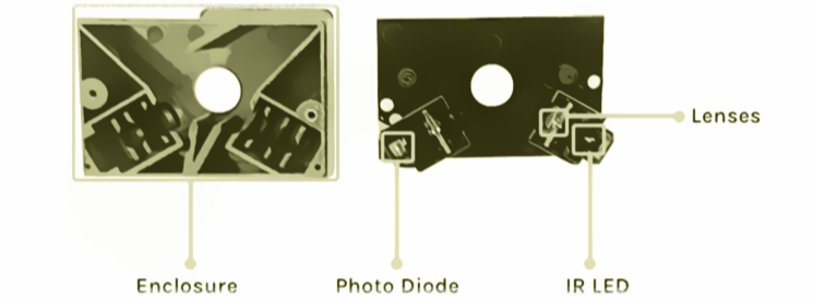
The GP2Y1014AU0F Dust sensor’s operation is simple and straightforward.
The light-emitting diode (light source), the photodiode (detector), and a pair of lenses are the three basic components inside the sensor.
The LED and Photodiode within the sensor are positioned in such a way that the two optical axes cross the sensor’s detecting region.
When dust or smoke reaches the sensor’s detecting area, the light within the sensor is reflected by the dust or smoke, causing the photodiode’s current to vary in proportion to the quantity of detected light.
And we get the desired output from our sensor by converting and amplifying the current value to voltage value using correct circuitry.
Only two of the six pins are required to function with the sensor.

The first one turns on the LED, while the second one outputs the sensor’s analogue signal.
The pulse driving of the LED requires the above-mentioned resistor, R1=150, and capacitor, C1=220uF.
The module will not function without the resistor and capacitor.
To retrieve the necessary data from the sensor, you must use a 10ms pulse with a pulse width of no more than 0.32ms to activate the LED.
After the trigger pulse is given to the LED, we should sample the signal after 0.28ms, as indicated by the datasheet.
Dust Sensor Module GP2Y1014AU0F – Parts
Because of the sensor’s structure, it’s impossible to indicate all of the important components in a single image, therefore we’ve split the GP2Y1014AU0F parts marking into two images.
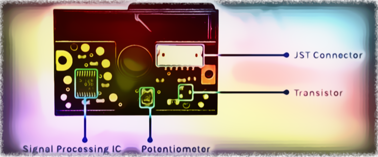
When the front cover of the sensor module is opened, you can view the PCB within.
The primary processor IC for processing data from the photodiode, a potentiometer, and a transistor that operates the LED are all included on the PCB.
Aside from that, the VCC, ground, and output data are all connected through a JST connection.
Dust Sensor Circuit Diagram for Arduino GP2Y1014AU0F
Now that we know everything there is to know about the GP2Y1014AU0F Dust Sensor, we can connect all of the necessary wires to Arduino and write our code to read the data from the sensor module.
The GP2Y1014AU0F Dust Sensor with Arduino Connection Diagram is shown below.
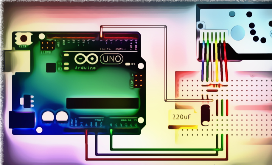
The GP2Y1014AU0F Dust Sensor is extremely simple to connect to an Arduino.
As we saw in the last section, this sensor sends data through a fluctuating voltage at the output pin.
As a result, we’ll utilise the Arduino’s ADC to translate and calculate the data into a recognised number.
We also need to connect the sensor’s LED enable pin to one of the Arduino’s GPIO pins; this is the white wire that is linked to the Arduino’s D7.
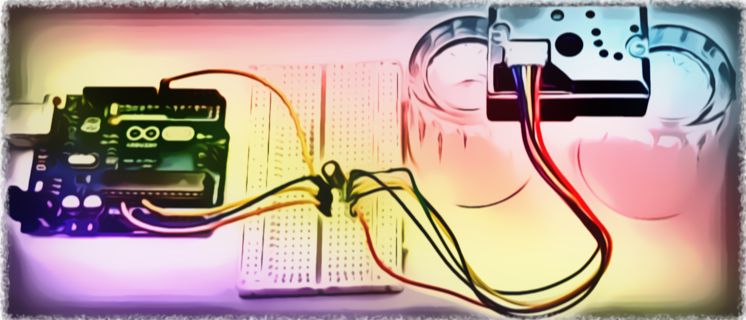
Finally, a 150R resistor and a 220uF capacitor are required.
The resistor and capacitor form an RC timer circuit, in this instance a pulse driver circuit, which is required for the device’s steady functioning, and the values are recommended per the datasheet.
Code
/*

 Interfacing Sharp Optical Dust Sensor GP2Y1014AU0F with Arduino

*/

#define measurePin = 0; //Connect dust sensor to Arduino A0 pin

#define ledPower = 7;   //Connect 3 led driver pins of dust sensor to Arduino D2

int samplingTime = 280; // time required to sample signal coming out   of the sensor

int deltaTime = 40; //

int sleepTime = 9680;

float voMeasured = 0;

float calcVoltage = 0;

float dustDensity = 0;

void setup(){

  Serial.begin(9600);

  pinMode(ledPower,OUTPUT);

}

void loop(){

  digitalWrite(ledPower,LOW); // power on the LED

  delayMicroseconds(samplingTime);

  voMeasured = analogRead(measurePin); // read the dust value

  delayMicroseconds(deltaTime);

  digitalWrite(ledPower,HIGH); // turn the LED off

  delayMicroseconds(sleepTime);

  // 0 - 5V mapped to 0 - 1023 integer values

  // recover voltage

  calcVoltage = voMeasured * (5.0 / 1024.0);

  // Chris Nafis (c) 2012

  dustDensity = 170 * calcVoltage - 0.1;

  Serial.println(dustDensity); // unit: ug/m3

  delay(1000);

}
Being Neutral is the master key to your growth with some patience
KP
“Be Calm and Compose, Happy and Content” – KP
Forgive but never forget, Bcas if u don’t learn from an experience u will never get success
KP
Helping Hands.