The EyeWriter is a low-cost eye-tracking device with bespoke software that allows graffiti writers and artists with Amyotrophic Lateral Sclerosis (ALS) to create entirely with their eyes.
The eyewriter design was based on a pair of spectacles in the initial design, as illustrated here:
Since that first video, we’ve been tinkering and improving the project, and we’ve come up with a new design we’ve dubbed “eyewriter 2.0,” which increases the device’s accuracy and allows individuals with slightly shifting heads to utilise an eye tracker as well.
The original eyewriter was created for TEMPT1, a disabled Graffiti artist, and is meant to be worn on a perfectly immobile head.
People with slightly moving heads, such as MS sufferers and people who wear spectacles, can utilise the 2.0 version, which employs a camera and LED system located distant from the head.
Step 1: Overview
The core concept is that we’ll do a few of things.
We’ll start by building LED illuminators for the screen’s sides and centre.
Second, we’ll hack the PS3 eye camera to obtain vertical sync (the time when a frame of video is recorded) and make it IR sensitive.
Finally, we’ll write and construct the arduino / cirucit that will control the blinking.
Finally, we’ll build up the system’s foundation and go over the software’s fundamentals.
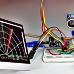
Technically, the 2.0 system works by strobing three infrared illuminators every frame.
It employs the centre illumination (placed around the camera lens) on even frames and the two side illuminators on odd frames.
The pupil appears bright on even frames because the IR light is reflecting off the back of your eye, similar to the red eye phenomenon.
Your pupil seems black in odd frames.
We can isolate and track the pupil in real time because of the difference between the two.
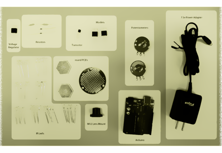
Step 2: Make a list of the parts you’ll need.
To begin, we’ll need quite a few things to build this gadget.
Please examine this image and this complete components list pdf to get an idea of what we’ll be working with.
Step 3: OpenFrameworks and EyeWriter software
To create and run the Eyewriter 2.0, you’ll need a few software packages.
We’ll go over how to download and install an IDE, openFrameworks, and the eyeWriter programme in this phase.
A. Environment for Integrated Development (IDE)
An integrated development environment (IDE) is a software application that gives computer programmers all the tools they need to create software.
If you need to run openFrameworks, download and install an Integrated Development Environment (IDE).
openFrameworks is a set of open-source software that allows you to create your own
Openframeworks is a c++ library that helps with the creative process by offering a simple and straightforward framework for experimenting.
If openFrameworks is needed, download and install it.
Step 4: Camera and Arduino Software
We’ll also have to put in two more pieces of hardware.
Our PS3 eye camera will be able to interact with our computer using Macam, and our physical hardware will be able to interface with our software via Arduino.
Step 5: Load the Arduino code
A. Arduino Code (Only for PS Eye)
In the Arduino IDE software, load the Arduino EyeWriter sketch “apps/eyewriter-xxxxxxx/eyeWriterTracker/StrobeEye/StrobeEye.pde.”
In order for the eyewritter programme to identify the hardware, this must be done.
Connect your Arduino board to your computer and upload the sketch.
If you’re new to the Arduino environment, start with the Getting Started instructions.
Step 6: Power Adapter
Adapter for Power
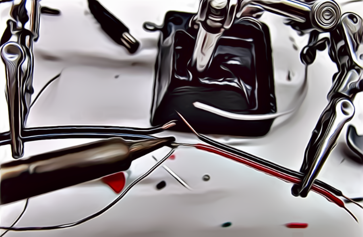
You will cut the wire of a power adapter to power your breadboard in this stage.
Your 7.5 Volt Power Adapter’s connection jack should be clipped off.
here’s an image
Determine the positive and negative wires in the adapter’s exposed cable using a Voltmeter.
Solder the red wire to the adapter’s positive wire and the black wire to the adapter’s negative wire with a short strip of red and black wire.
Tape the exposed wires separately to keep positive and negative wires separate, then tape them together to guarantee no wires are exposed.
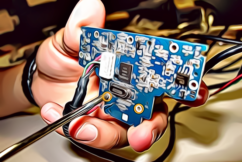
Step 7: Infrared LEDs
8 IR Light-Emitting Diodes (LEDs) with a tiny spherical Printed Circuit Board (PCB).
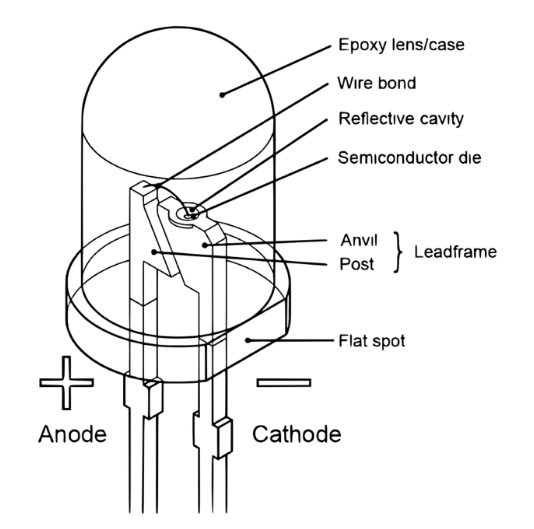
You’ll need to know the positive and negative ends of each LED to construct LED arrays on PCBs.
The anode (positive) is the longer leg of the LED, while the cathode (negative) is the shorter leg (negative)
There will be a flat patch on the cathodes side of the lens on most LEDs.
Take notice of the way the wire bond points in relation to positive and negative from above.
Set up a circuit with 4 LEDs in series and another set of 4 LEDs in series in parallel.
Clip the LEDs’ legs together and solder them.
Solder around 2 feet (60 centimetres) of red and green intercom wire to the LED circuit’s positive and negative ends after soldering the LED legs together to make the circuit.
Build the circuit below to test the LED PCB panel.
Examine your IR LEDs to determine whether they are shining a faint red.
To keep all connections in place, cover the back of the LED PCB panel with hot glue after checking that your IR LEDs are working.
To make another LED PCB panel, repeat steps 1 through 5.
Build a circuit of four parallel sets of four LEDs in series on the PCB’s rim.
The LEDs should be placed in such a way that the PS Eye camera may fit through without obscuring the LEDs.
Solder wiring to link all four positive and negative ends together, putting all four LED sets in parallel, then soldering the LED legs together to make the circuit.
Solder around 2 feet (60 centimetres) of red and green intercom wire to the positive and negative ends of the LED circuit.
Build the circuit below to test the bigger LED PCB panel.
Examine your IR LEDs to determine whether they are shining a faint red.
To keep all connections in place, cover the back of the LED PCB panel with hot glue after checking that your IR LEDs are working.
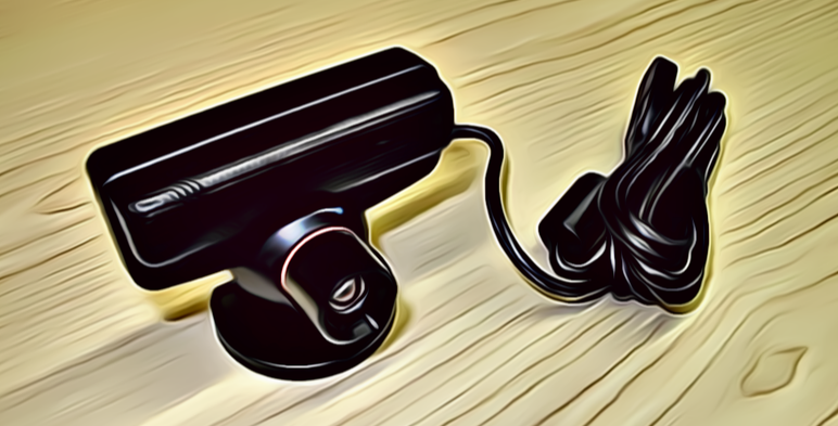
Step 8: Preparing to Hack the PS Eye Camera
We’ll go through how to disassemble a PS Eye camera in this phase.
This is required in order to replace the camera’s lens, install an infrared filter, and connect the v-sync.
Get in a PlayStation Eye camera. You should use the camera at your own risk because it will be modified, voiding the warranty.
Remove the four plastic screw covers from the casing’s rear.
Remove the four screws from behind the screw caps.
Keep these screws in case you need them in the future.
Pry the rear part of the case off with all four screws removed.
A hammer and a flathead screwdriver, or a set of pointed pliers, should suffice.
It takes a lot of power, so be careful not to harm yourself or damage anything within.
here’s an image
Remove the two bottom screws beside the plastic holder and pull the cable away.
Also keep these screws.
here’s an image
Remove the stand from the equation.
Remove the five screws that go around the perimeter of the board (two screws on the side, three screws on top).
Also keep these screws.
here’s an image
Lift the board out of the front shell after removing all five screws.
On the top of the board, there are four microphones.
Clip the microphones using wire cutters because they will not be utilized.
here’s an image
The PS Eye board is now ready to be wired.
The wiring for the Vertical Synchronization (V-Sync) and Ground joints on the PS Eye board will be connected in the following steps.
Step 9: Using VSync to Hack the PS Eye Camera
We’ll go through how to remove the v-sync from the camera in this phase.
The v-sync is an electrical signal generated by the camera that transmits the refresh rate of the camera.
It’s critical to get the camera’s v-sync working since it’s the only method to match the camera’s refresh rate to our infrared LEDs.
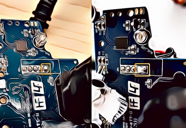
On your PS Eye board, find the Ground joint.
Some PS Eye versions feature five joints near the lens mount (see left image below), whereas others only have four (right image below).
The Ground joint is at the end of your model closest to the lens mount if it has five joints.
If your model has four joints, the Ground joint is at the end closest to the lens mount and is double the width of the others.
Cut around 2 feet (60 cm) of 4-color intercom wire and separate the red, green, and black and white colours.
On the board, look for the V-Sync via.
It’s the via in the image below that’s circled.
Here is an example of an image.
The VSync hotspot is located on the front of the PCB, immediately above the R19 resistor, for more recent models of the PSEye camera (recognised by the golden rim surrounding the board).
Here is an example of an image.
A fresh model has just been offered on the market (v9.2)
In this figure, you can see how to recognise it and where to discover the vSync location.
Carefully pivot the knife tip on the via and scrape off enough insulating layer to reveal the metal contact underneath with a sharp knife.
The exposed V-Sync via requires the red wire to be connected, however the wire is too thick to solder cleanly to the little via, thus a 30 gauge wire will be used in between.
Strip the ends of two 30 gauge wire pieces.
Reduce the length of the red wire, then solder one end of the 30 gauge wire to the red wire’s end.
A test should be done before connecting the 30 gauge wire to V-Sync to check that all connections are proper.
Make the circuit shown below.
The LED on the breadboard should flash fast when the 30 gauge wire meets the V-Sync via.
Carefully attach the 30 gauge wire to the exposed V-Sync via with thin 0.022 inch (0.56 millimetre) solder.
Make sure the LED on the breadboard is blinking to confirm.
Step 10: Finishing the PS Eye Camera Hack
Remove the two screws that keep the lens in place.
Take care not to damage the V-Sync connection.
Remove the lens while keeping both screws.
Measure the new lens mount’s square opening.
Cut a square from the filter sheet that is just a smidgeon smaller than the lens mount opening and insert it there.
Screw in the replacement lens mount after the filter is in place.
Because the new lens mount is a bit too big for the board, you’ll have to use some effort, and one screw will go in at an angle.
Screw the new lens into the board’s new lens mount.
Cover and seal the V-Sync connection with hot glue.
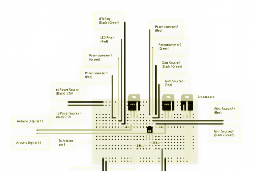
Step 11: Complete the circuit
We’ll teach you how to put the circuit together on the breadboard in this stage.
This is the first step in getting the eyeWriter software to operate with your Arduino.
Build the circuit shown in the diagram below.
The EyeWriter code is ready for live camera input after completing the whole circuit.
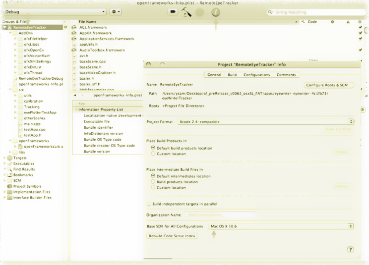
Open “apps/eyewriter-xxxxxxx/eyeWriterTracker/bin/data/Settings/inputSettings.xml” and change the mode tag from 1 to 0 to convert from video demo mode to live camera mode.
Build and run the source code in the “apps/eyewriter-xxxxxxx/eyeWriterTracker/RemoteEyeTracker.xcodeprof” file.
With input from the PS Eye camera, the Tracking screen should load.
Step 12: Create a Wooden Foundation
We’ll speak about how to make a portable wood basis in this phase.
It’s interesting to construct this so that your system can rest on a solid foundation.
This makes testing, calibrating, and working with the eyeWriter a lot easier.
The following is a list of materials and pieces that will be required for the base:
2 x 5/16 wood rods (about 20 inches in length) (A)
2 x 5/16 inch wood rods (about 1 1/2 inch length) (D)
1 piece of wood, 20 x 4 x 1/2 inch (B)
3 x 1 3/4 x 1 3/4 inch wood parts 3 x 1 3/4 x 1 3/4 inch wood pieces 3 x 1 3/4 x 1 3/4 inch wood (C)
drill bit with a diameter similar to the diameter of the wood rods
The following is a list of materials and pieces that will be required for the base:
2* 5/16 wood rods - approx. 20 inches long (A)
2* 5/16 wood rods - approx. 1 1/2 inch long (D)
1* 20 x 4 x 1/2 inch wood piece (B)
3* 3 x 1 3/4 x 1 3/4 inch wood pieces (C)
drill bit with approx. diameter of the wood rods
step 1: line the two parts (C) with the third piece (C) as indicated in the figure, clamp them together, and drill 3/4 inch close to the edge through them.
step 2: arrange the two parts (C) with the identical holes aligned on the edges of the piece (B), clamp the aligned (see figure for example), and drill a hole through them on the (B) piece until about 1 1/2 inch deep.
Use the small wood rods to go through the holes in the piece’s (B) edges and each of the components (C)
here’s an image
step 3: drill a hole large enough for the tripod head mount screw to fit through.
here’s an image
step 4: after assembling the bottom bar (B) and edge pieces (C), put the rods (A) through the holes, aligning them with the length of the bottom bar.
here’s an image
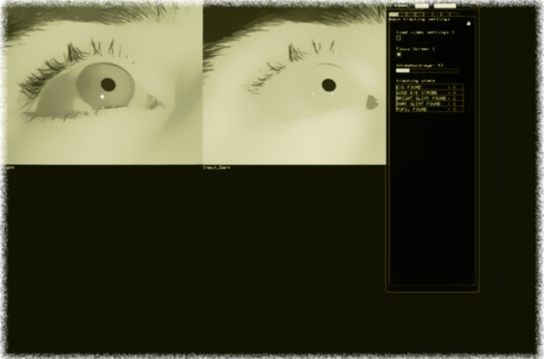
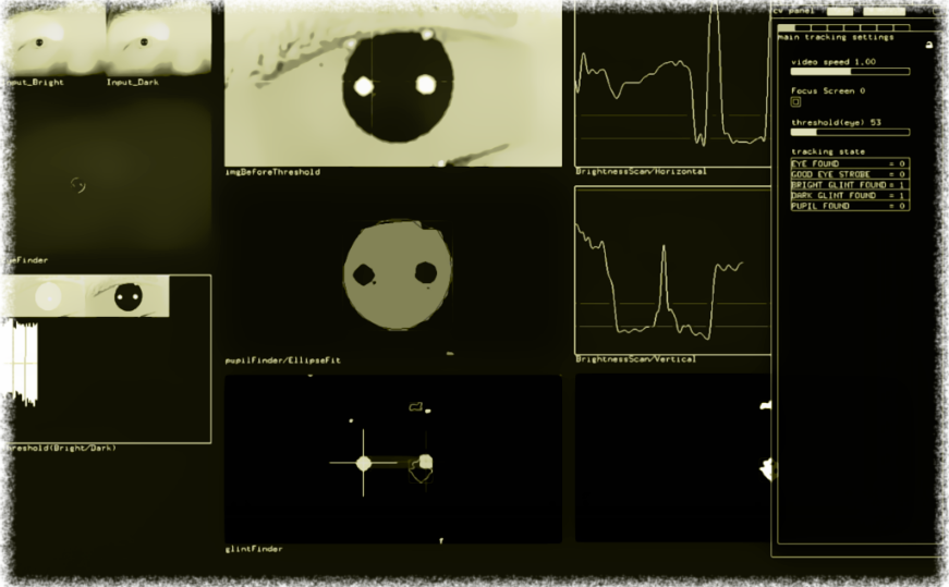
Step 13: Setup & Tracking Screen for EyeWriter Software
Select Focus Screen from the first tab of the Computer Vision (CV) panel on the right to focus your camera.
Deselect Focus Screen to return to the Tracking screen, then rotate the lens of your camera until both video feeds seem crisp.
On the first tab of the right panel, select load video settings.
For the PS3 Eye Camera, a bright, balanced image with minimum noise is ideal.
A sample picture is provided below.
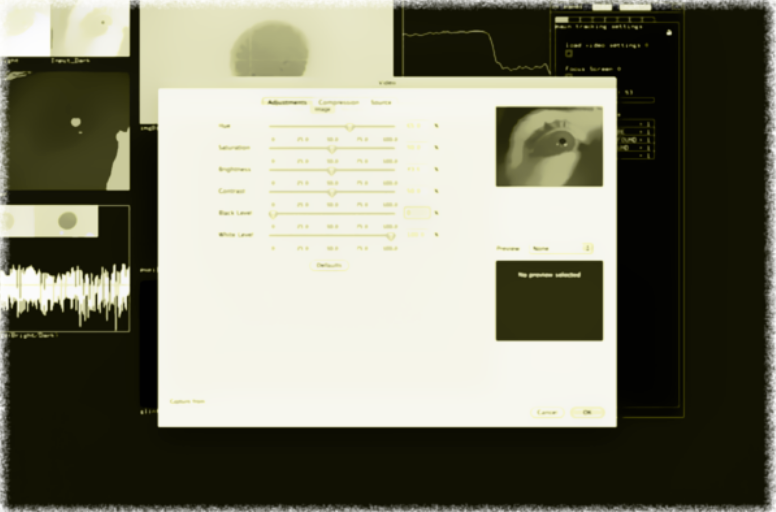
Slide the Gain and Shutter parameters back and forth under the Webcam menu until the footage appears perfect.
If you have a faster machine, change the Frames per second (Fps) to 30 under the Compression tab.
Set your FPS to 15 if you’re using a slower machine.
Step 14: Calibration Screen using EyeWriter Software
Press the spacebar to get instructions, then press the spacebar again to begin.
Keep an eye out for the red dots as they come.
The blue lines at the conclusion of the calibration show any calibration errors.
If any lengthy blue lines appear, reset the calibration and restart by using the spacebar.
Keep your gaze fixed on the Catch Me box.
The hue of the box will turn green as you gaze at it.
The box gets captured when it turns completely green and appears someplace else.
To test your eye-tracking calibration, keep catching the boxes.
Step 15: Creating a Drawing with EyeWriter Software
By default, drawing mode is suspended.
You may turn on or off the backdrop grid before you start sketching.
Pausing may be used to swap the backdrop grid at any moment.
Switch to recording mode by gazing at the stopped button to begin sketching.
The button will turn green and switch to recording as you gaze.
Vector points are used in drawing.
To make a point, stare at a spot on the canvas for approximately a second.
To make a point, your green eye-tracking circle must remain perfectly stationary.
A stroke will link the spots as you add them.
These strokes can be used to make shapes and letters.
Look at the next stroke button to start a new line.
You may undo point, which eliminates the last point drawn, or undo stroke, which removes the complete last stroke made, to modify what you’re drawing.
Stare at the next letter to save the current form or letter and go on to the next one.
Your most recent letter will show at the top of the screen, and you’ll be given a new blank canvas on which to create a new letter.
When you’ve completed creating your shapes and letters, use the NEXT MODE button to advance to Positioning mode.
POSITIONING
All of your letters are picked and ready to be positioned by default.
By looking at Select Letter, you may select specific letters.
You may rotate your selection right (clockwise) or left (counter-clockwise) using Select Rotate.
You may use Select Shift to move your selection up, down, left, and right.
Select Zoom allows you to downsize and increase your selection by zooming out and in.
Your letters will be placed side by side in the sequence you drew them.
When you’ve completed arranging your shapes and letters, go to Effects mode by looking at NEXT MODE.
Step 16: Typing with EyeWriter Software
Focus on the key you want to push.
The colour of the keys will change from green to blue as you gaze at them.
here’s an image
It has been pushed when the key flashes blue.
At the top of the screen, you can see what you’ve entered.
Press the Pronounce key on the bottom left of the screen to speak the words written.
Pronounce WORDS OFF/ON toggles the option to speak words automatically once they are written and a space is placed in the middle right of the screen.
The CAPS OFF/ON key is located in the bottom right corner of the screen.
This toggles caps lock on and off, and it’s essential to utilise the number keys’ alternative characters (! @ # $ percent, etc.).
Think – Process – Observe – Action
KP
“The person who can accept their mistakes, Will grow faster than others. bcas once you start accepting it, you’ll try to take care of it and never repeat it” – KP
Whatever you want to do just do it, Don’t think about result. Miss someone – call them listen their voice, like someone – tell them, love someone – not express too much, help someone – without accepting anything in return, Angry – Take deep breath and see the stars in the sky, anxious – Meditate, Happy – Calm and don’t excite, Think – Positively, Network – Well, Exercise – Daily, Eat – Whatever you love to eat, Build – Faith, Worry – Less, Read – More, Live – Forever
KP
Helping Hands.