Supply and components
- Espressif ESP8266 ESP-01
- Arduino UNO
- Jumper wires (generic)
- LED (generic)
This project’s description
Components Required
- ESP8266 – Al-Cloud Inside (Black model: Flash size 8Mbit = 1MByte )
- Breadboard
- Arduino UNO;
- Wires (jumpers);
- Laptop;
- Patient (a lot).
1. Before updating the firmware
1.1) The Arduino ATMega chip must be removed.
The yellow LED on the Arduino should be turned on.
1.2) The firmware upgrade does not utilise GPIO2.
1.3) At 3.3V Arduino ports, just VCC and CH PD (CHip Down) must be connected.
1.4) At GND Arduino ports, only GND and GPIO0 (general purpose input/output) must be connected.
GPIO0 in GND is used to programme the ESP8266.
2. Firmware Update Wiring

3. Download the Firmware Update Software

3.1) FLASH DOWNLOAD TOOLS v2.4 1509
3.2) NONOS SDK V1.5.4 AT V1.1 on ESP8266
3.3) Firmware from the manufacturer: ai-thinker-v1.1.1.bin
4. Firmware Upgrade
4.1) Launch the Flash Download Tools application.
4.2) Fill in the following fields:
ESP8266 NONOS SDK V1.5.4AT binblank.bin >>> ESP8266 NONOS SDK V1.5.4AT binblan
0xFE000
ESP8266 NONOS SDK V1.5.4AT binesp init data default.bin >>> ESP8266 NONOS SDK V1.5.4AT binesp
0xFC000
ESP8266 NONOS SDK V1.5.4AT bin512+512user1.1024.new.2.bin >>> ESP8266 NONOS SDK V1.5.4AT bin512+512user
0x1000
>>> ai-thinker-v1.1.1.bin
0x0
4.3) Set the SPI Flash parameters as follows (Note: according to these wikis…
…all ESP8266s support SPI MODE “DOUT”).

4.4) Select START and wait for the upload to complete.
4.5) Exit the Flash Download Tools application.
5. After Firmware Deployment
RX, TX, and GPIO0 connections should all be disconnected.
5.2) Disconnect Arduino from the USB port.
5.3) Plug the Arduino back into the USB port.
These pins should be utilised at this point:
—> VCC and CH PD
3.3v Arduino
—> GND
GND on Arduino
—> RX
RX Arduino
—> TX
TX Arduino
5.4) Launch the Arduino IDE.
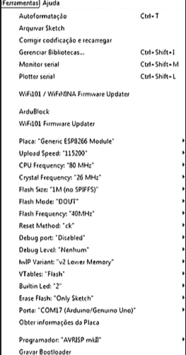
5.5) Select Tools — Board — Generic ESP8266 Module from the drop-down menu.
5.6) Choose the appropriate ESP settings:

5.7) Switch on your Serial Monitor.
5.8) If you disconnect and reconnect the CH PD cable at this point, you should see some characters on the serial monitor.
To send/receive AT messages, the CH PD wire must be connected.
If no characters appear, something is amiss, and you must reinstall the firmware.
5.9) Perform the following AT commands:

Final Thoughts
This ESP8266 model’s baudrate is 115200 bits per second.
After the firmware upgrade, remember to disconnect RX, TX, and GPIO0.
If you don’t, the firmaware update will have to be done again when you shut off your ESP8266.
Dream IT, Wish IT, Do IT,
kp
“If you want a rainbow, you have to endure the rain” -KP
Helping is a nature, You can’t learn it
KP


