Drawing Robot/Pen Plotter/Drawing Machine is an Open Hardware version of the well-known AxiDraw pen plotter.
Hardware
TSX00083Drawing Robot/Pen Plotter/Drawing Machine is an Open Hardware version of the well-known AxiDraw pen plotter, which can write or draw on nearly any flat surface.
It can handle a wide range of applications by writing with pens, permanent markers, pencils, and other writing utensils.
Its one-of-a-kind design includes a writing head that extends outside the machine, allowing it to draw on items that are larger than the machine.
Because of the machine’s core XY extending design, it can be put over the book, which is its major benefit.
This Drawing Robot/Pen Plotter/Drawing Machine looks a lot like the AxiDraw, which is a commercially available product.
It’s controlled by an Arduino Uno, has a CNC Shield, and runs on GRBL firmware.
The cost of building the Drawing Robot varies between $75 and $150, depending on where you buy your parts and whether you already have some, such as the Arduino.
24 * 30 cm is the maximum sketching area.

Step 1: Gather the necessary parts and materials
Nema 17 stepper motors (two)
2 × M8 x 450mm Linear Rods for X Axis
2 × M8 x 350mm Linear Rods for Y Axis
2 x 3mm Linear Rods for the Z Axis (you can get it from old CDROM)
1 × Threaded Rod M8 x 480mm8 x LM8UU Bearings
1 x Sg901 x Spring 5m Servo (from ball point pen)
2 x GT2 Pulley, 16 teeth
Bearing 624zz (Set of 5)
1 × 2000mm GT2 belt
1 × Arduino Uno
1 x CNC Shield
2 x A4988 stepper drivers, each with its own heatsink
6 x Jumpers
1 × 12V 2A Power Supply
Nuts
M3-0.5 x M4-0.7 x M3-0.5 x M4-0.7 x M3-0.5 x M4-0.7
18 x 4 x 5/16in
Amazon\sScrews
13 × M3-0.5 x 16mm Phillips
4 pcs M3-0.5 x 6mm Phillips
5 pcs M4-0.7x 35mm Phillips
1 × M3-0.5 x 20mm Hex
Washers
washer, 4 x 5/16in
M3 washers (four)
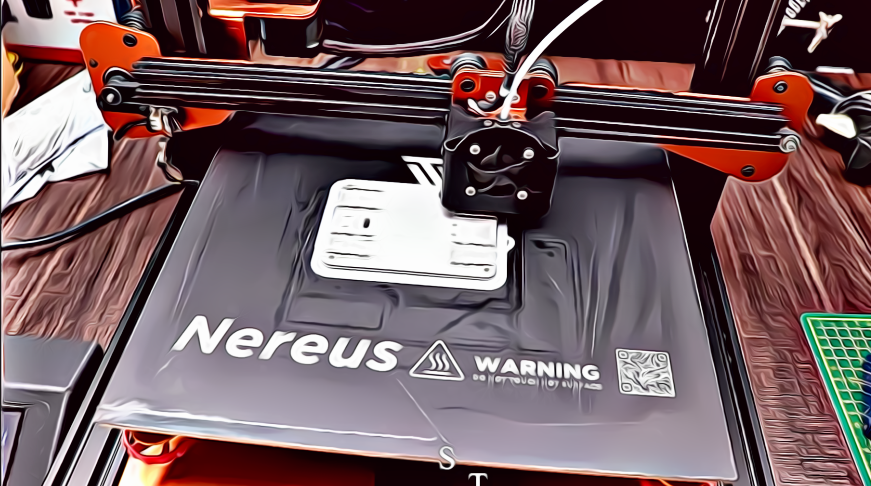
Step 2: 3D Printing
Thingiverse is where you can get the files.
Cura or another slicer may be used to open the 3D models.
Use a 75 percent infill on all portions (a 70 to 100 percent infill would suffice).
All pieces were printed with a layer height of 0.10–0.20 mm.
PLA was used to print this.
Use the Penholder, Slider, X Support L, and X Support R as supports.
Note: The longest component took around 10 hours to print, while the shortest took only 30 minutes.
PLA is suitable for this project.
On BuildTak, I print at 200°C.
There are no rafts or brims required for any of the sections.
Only the pen holder and the upright Z axis end plate should be supported, in my opinion.
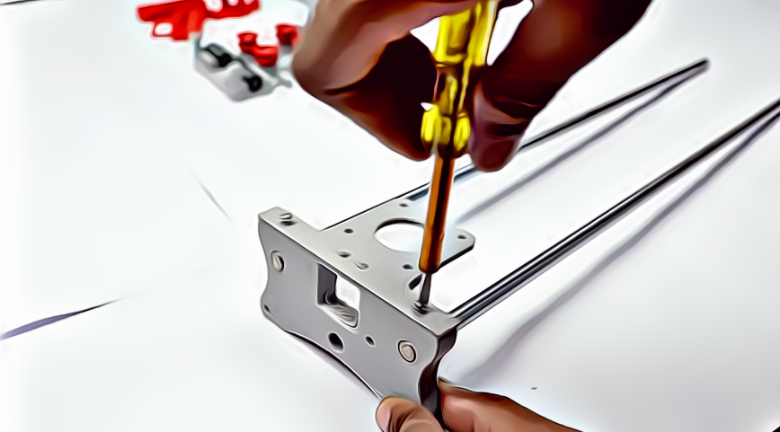
Step 3: Put the X-Axis together
Keep in mind that you’ll need two 350mm and two 450mm linear rods.
Insert the (2) 450mm linear rods into one of the x-support parts.
You may need to smooth up the holes with a round file before inserting the rods. You may also use a rubber mallet to assist insert the rods.
The threaded rod should now be inserted into the hole below.
On both sides of the x-support section, feed a 5/16in washer and 5/16in nut.
Step 4: Put the X-Axis Bearing Together
Slide the clamshell through the 450mm linear rods (X-axis).
Attach the final X-support on the linear rods with a rubber mallet once again.
Make sure the rods are evenly spaced on both sides.
Thread the opposite end of the threaded rod through the X-hole. support’s
To keep the X-support in place, add the last set of nuts and washers.
You may now add (2) Phillips M3-0.5 x 16mm screws per X-support to assist keep the linear rods from slipping now that the X-axis is complete.
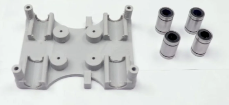
Now you must push the LM8UU bearings into their proper positions on the top and bottom clamshells (each clamshell requires four bearings).
Push four 624zz bearings through the idler pulleys that were 3D-printed.
When assembling the Y-axis, save the fifth bearing for later.
Construct the X-Axis (Carriage)
With the idler pulleys fitted, get (4) M3-0.5 x 20mm screws, (4) M3 nuts, (4) M3 washers, and (4) 624zz bearings.
Feed a washer through one screw; the washer will rest on the bearing.
The bearing will be secured in place by a nut at the bottom of the carriage.
Slide the clamshell through the 450mm linear rods (X-axis).
Attach the final X-support on the linear rods with a rubber mallet once again.
Make sure the rods are evenly spaced on both sides.
Thread the opposite end of the threaded rod through the X-hole. support’s
To keep the X-support in place, add the last set of nuts and washers.
You may now use (2) Phillips M3-0.5 x 16mm screws to complete the X-axis.
each X-support, screws to protect the linear rods from slipping
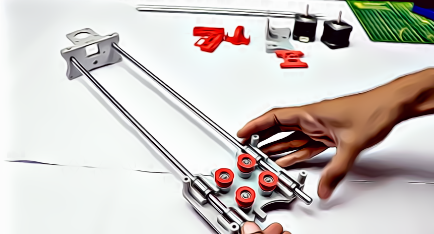
Step 5: Put the Y-Axis together
Y-Back
Using a rubber mallet, insert the (2) 350mm linear rods into the Y-back piece.
Obtain one M4-0.5 x 35 screw, one M4 nut, and the fifth 624zz bearing.
To fasten the linear rods, get two M3-0.5 x 16 screws.
When screwing the Y-back piece together, slide the bearing in.
Y-Front
Slide the linear rods/Y-back piece through the LM8UU bearings and use a rubber mallet to secure the Y-front piece.
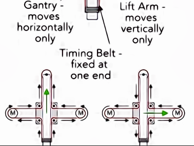
Step 6: Put the X-Y Axis Together (Belt)
To make it easier to guide the GT2 belt through the clamshell, use a set of needle nose pliers.
Take the two ends of the belt and thread them through the Base Slider’s “teeth.”
The belt should be snug, not slack.
It is common for the clamshell to not move freely after the GT2 belt is installed.
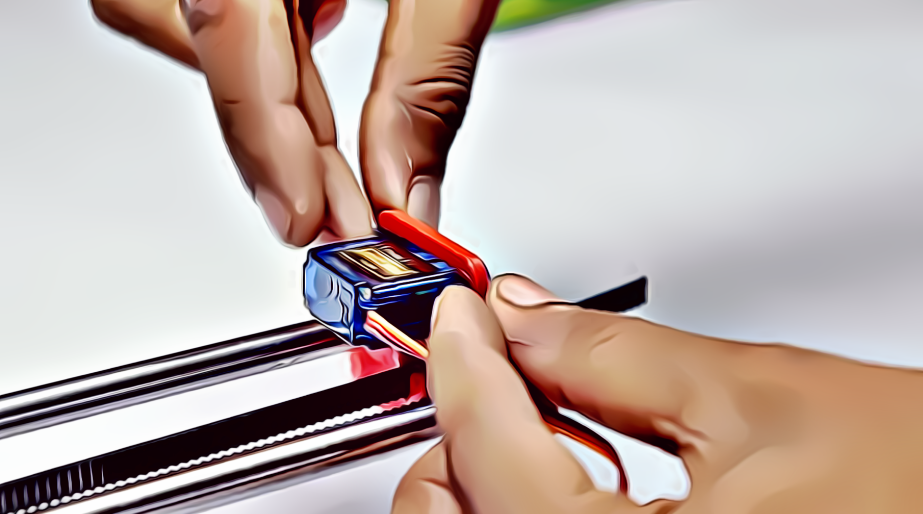
Step 7: Put the Z-Axis together.
2 3mm linear rods and the 3D printed items listed below (Slider, Pen Holder, Base Slide, 3MM Metric Thumb Screw)
Take one Hex M3-0.5 x 20mm screw and one Metric Thumb Screw and combine them.
To hold things together, use superglue.
You’ll need three M3-0.5 x 16mm screws to fasten the Base Slide to the Y-Front portion.
To keep it in place, you might need to use three M3-0.5 nuts.
To make one piece, push the Slider and Pen Holder together.
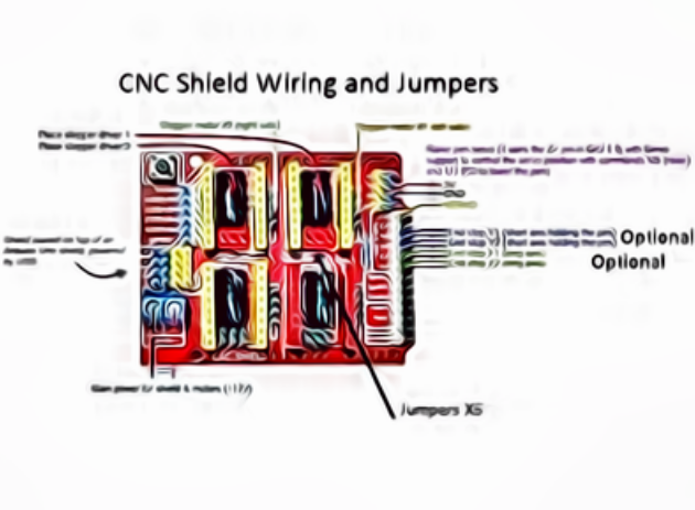
Step 8: ELECTRONICS
ELECTRONICS
I recommend that you utilise the Arduino uno CNC Shield.
Prepared for your whole circuit
1) A4988 Stepper Motor Driver, 4 pcs
2) A4988 Expansion Board Driver
3)Arduino UNO (Arduino Uno)
To begin, take the hit sink and place it on the A4988 motor driver.
Attach four A4988 stepper motor drivers to the A4988 driver module on the extension board, then connect the arduino to the expansion board and connect all wire.
The shield also includes built-in micro stepping control, which means that instead of utilising full or half steps like a huge CNC, we can have the motors move by 1/16 or 1/32 of a step to move the laser with the greatest accuracy.
The motors, on the other hand, will use more electricity and become hotter more quickly.
Short several of the mode pins together to use the micro stepping modes.
Various combinations result in various resolutions.
Take a look at the diagram to see the many combinations that are available.
After the shield has been configured, connect the A4988 drivers and the rest of the electronics.
Use a multimeter to locate the stepper motor coils.
You have a coil if there is resistance between the two wires.
The coils are represented on the diagram by two wires of the same colour.
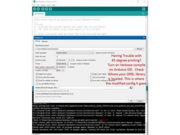
Step 9: APPLICATION SOFTWARE
Inkscape is a graphics design software programme (draw or import graphics)
MI GRBL Extension for Inkscape (convert graphics to G-Code)
G Code Sender (Universal) (sends the G-Code to the robot causing drawing motion)
The Arduino firmware is GRBL (programmed into the Arduino Uno)
Be Confident, Have Positive Gesture, Convincing Body Language, Disciplined Actions, Dedicated Approach, Be Determined, Be Transparent
KP
“Update your mindset with time to improve your growth and business, Have a timely pivot” – KP
Helping Hands


Ik was op zoek naar dit project van lange tijd, ik ben je echt dankbaar heel erg bedankt 🙂